|
TGX 1.1.4
A tiny 2D/3D graphics library optimized for 32 bits microcontrollers.
|
|
TGX 1.1.4
A tiny 2D/3D graphics library optimized for 32 bits microcontrollers.
|
This page introduces the TGX 3D renderer and explains the normal path from a 3D object to pixels in a tgx::Image.
/examples/.TGX is a small software rasterizer for embedded systems. It is not a scene graph and it does not own the display driver. A sketch gives TGX a framebuffer, a Z-buffer if needed, a camera, a model transform, a shader state, material and light state, then calls drawing methods. The sketch remains responsible for clearing buffers and uploading pixels to the screen.
The tutorial is organized in the same order:
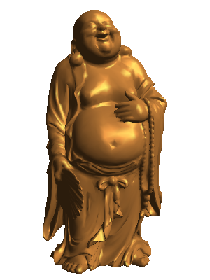
The buddha mesh rendered by TGX's 3D engine. See examples/CPU/buddhaOnCPU/.
The main 3D class is tgx::Renderer3D. It transforms vertices, clips triangles, projects them to a 2D viewport and writes pixels into a destination tgx::Image.
Renderer3D is immediate-mode: it does not store a list of objects. It stores the current render state. You set that state, draw one object, then change the state and draw the next object.
| State | What it controls | Main methods |
|---|---|---|
| Destination | Destination image, viewport and tile offset. | setImage(), setViewportSize(), setOffset() |
| Depth buffer | Optional per-pixel depth testing. | setZbuffer(), clearZbuffer() |
| Camera lens | Perspective, frustum or orthographic projection. | setPerspective(), setFrustum(), setOrtho() |
| Camera pose | Where the camera is and where it looks. | setLookAt(), setViewMatrix() |
| Object pose | Placement, scale and rotation of the object being drawn. | setModelMatrix(), setModelPosScaleRot() |
| Rendering path | Shading mode, texturing, Z-buffer use and texture sampling. | setShaders(), setTextureQuality(), setTextureWrappingMode() |
| Appearance | Material, texture and lights. | setMaterial(), setLight(), setSpotLight() |
| Visibility/debug | Back-face culling, wireframe and point helpers. | setCulling(), drawWireFrameMesh(), drawDots() |
It is useful to keep ownership clear:
| Owner | Stores |
|---|---|
| The sketch | Framebuffer memory, Z-buffer memory, display upload and frame timing. |
| The renderer | Current camera, projection, model matrix, shader state, material, texture and light state. |
| Mesh data | Vertices, normals, texture coordinates, material tables and texture references. |
| A draw call | Consumes the current renderer state and the geometry passed to that call. |
Renderer state persists until it is changed. If two objects need different materials, shaders or model matrices, set that state before each corresponding draw call.
A minimal frame can look like this:
In larger sketches, keep this separation:
| Moment | Typical work |
|---|---|
| Initialization | Allocate buffers, create the image, create the renderer, choose compiled shader variants. |
| Beginning of a frame | Clear the image and Z-buffer, update camera/projection if needed. |
| For each object | Set model matrix, shader, material and texture state, then draw. |
| End of frame | Upload the image, display it on CPU, or save it. |
TGX draws into an existing tgx::Image. The sketch decides where that image memory lives:
The image is the memory that receives pixels. The viewport is the virtual screen size used by projection and pixel mapping. In the simplest case they have the same size:
Solid rendering usually also uses a Z-buffer:
ZBUFFER_t can be float or uint16_t:
| Type | Cost | Notes |
|---|---|---|
float | 4 bytes per pixel | Better precision. |
uint16_t | 2 bytes per pixel | Saves memory; can show more z-fighting. |
Clear the image and Z-buffer once at the beginning of each frame, not before every object.
To render without a Z-buffer, compile and select the SHADER_NOZBUFFER path. SHADER_NOZBUFFER is a real shader variant and must be present in LOADED_SHADERS if the sketch uses it.
The image can be smaller than the virtual viewport. This lets you render a large viewport in several tiles when a full framebuffer and Z-buffer do not fit in memory. The projection and viewport describe the final screen; setOffset() selects which part of that screen the current image represents:
3D rendering is mostly about moving points through coordinate spaces. A mesh vertex is not written directly to the framebuffer; it is transformed, clipped, projected and finally converted to pixels.

| Space | Meaning in TGX | Example |
|---|---|---|
| Model space | Coordinates stored in a mesh or passed to primitive drawing functions. | A unit cube centered at the origin. |
| World space | Scene coordinates after the model matrix places the object. | Several objects positioned relative to each other. |
| View space | Camera coordinates after the view matrix. | The camera is at the origin and looks along negative Z. |
| Clip space | Homogeneous coordinates after projection, before perspective divide. | Clipping happens here. |
| NDC | Normalized device coordinates after perspective division. | Visible x/y coordinates are roughly in [-1, 1]. |
| Image space | Destination pixel coordinates. | (0,0) is the upper-left pixel. |
The full pipeline is:

TGX uses a right-handed camera convention in view space: the camera is at the origin, looking toward negative Z, with Y pointing upward. In image space, TGX uses the normal tgx::Image convention: X goes right and Y goes down.
TGX uses small value types for 3D math:
| Type | Purpose |
|---|---|
tgx::fVec3 | A 3D point or vector using float coordinates. |
tgx::fVec4 | A homogeneous 4D vector, mostly useful around projection and clipping. |
tgx::fMat4 | A 4x4 floating-point matrix for transforms and projections. |
tgx::fBox3 | An axis-aligned 3D bounding box. |
A point and a direction both use (x,y,z), but they are not transformed the same way. Homogeneous coordinates encode the difference with w:
| Quantity | Homogeneous form | Matrix helper |
|---|---|---|
| Point | (x, y, z, 1) | fMat4::mult1() |
| Direction/vector | (x, y, z, 0) | fMat4::mult0() |
| Explicit 4D vector | (x, y, z, w) | fMat4::mult() |
Use mult1() for positions and mult0() for directions. This matters for normals, light directions and camera axes.
Common vector operations:
| Operation | TGX method/function | Used for |
|---|---|---|
| Length | norm2(), norm(), norm_fast() | Distances and normalization. |
| Inverse length | invnorm(), invnorm_fast() | Fast normalization. |
| Normalize | normalize(), normalize_fast() | Unit normals, light directions and camera vectors. |
| Dot product | dotProduct(a,b) | Lighting, angle tests and back-face tests. |
| Cross product | crossProduct(a,b) | Face normals and perpendicular axes. |
Normals describe surface orientation. For lighting and culling, normals and light directions should have length 1. Non-normalized normals usually produce dark, overbright or unstable lighting. Non-uniform model scale is a special case because normals cannot be transformed exactly like ordinary points; TGX keeps the runtime small and works best with normalized mesh normals and mostly uniform scales.
Renderer3D stores three main matrices:
| Matrix | Maps from | Maps to | Main methods |
|---|---|---|---|
| Model | Model space | World space | setModelMatrix(), getModelMatrix(), setModelPosScaleRot() |
| View | World space | View space | setViewMatrix(), getViewMatrix(), setLookAt() |
| Projection | View space | Clip space | setProjectionMatrix(), getProjectionMatrix(), setPerspective(), setFrustum(), setOrtho() |
The matrices are applied from right to left:
In a normal render loop:
setModelPosScaleRot() is the convenient form for most objects. Use setModelMatrix() when you already have a full matrix.
setLookAt() builds the view matrix:
The projection matrix acts like the lens. It controls what is visible and how depth changes apparent size:
| Projection | TGX call | Visual effect |
|---|---|---|
| Perspective | setPerspective(fovy, aspect, zNear, zFar) | Distant objects become smaller. |
| Frustum | setFrustum(left, right, bottom, top, zNear, zFar) | Explicit perspective volume. |
| Orthographic | setOrtho(left, right, bottom, top, zNear, zFar) | Object size does not depend on distance. |
| Custom | setProjectionMatrix(M) | Use your own projection matrix. |
After setProjectionMatrix(), call usePerspectiveProjection() or useOrthographicProjection() if the renderer cannot know which mode your custom matrix represents. The standard setPerspective(), setFrustum() and setOrtho() helpers do this automatically.
Changing the model matrix affects the next object. Changing the view matrix moves the camera. Changing the projection matrix changes the lens.
When debugging transforms, these methods are useful:
| Method | Converts |
|---|---|
| modelToNDC(P) | A model-space point to normalized device coordinates. |
| modelToImage(P) | A model-space point to image pixels. |
| worldToNDC(P) | A world-space point to normalized device coordinates. |
| worldToImage(P) | A world-space point to image pixels. |
Perspective projection uses a visible volume called a frustum, a truncated pyramid:

For perspective projection, fovy is the vertical field of view in degrees and aspect is normally viewport_width / viewport_height. If the aspect ratio is wrong, objects look stretched.
zNear must be positive and should not be too close to zero. A very small near plane reduces depth precision and can make Z-buffer artifacts more visible. zFar should be large enough for the scene, but not much larger than needed.
After projection and perspective division, TGX maps NDC coordinates to the virtual viewport described in Destination Image, Viewport and Depth Buffer. In a full-frame render, the viewport and image have the same size. In a tiled render, the projection is still computed for the full viewport, and only the image offset changes from tile to tile.
TGX separates two questions that are easy to confuse:
| Question | Where it is answered | Example |
|---|---|---|
| Which code paths exist in this binary? | LOADED_SHADERS, a template parameter. | Compile Gouraud + textured + Z-buffer paths. |
| Which path is active for the next draw call? | Runtime state, mainly setShaders(). | Draw this object as Gouraud textured. |
The renderer template is:
| Parameter | Meaning | Default |
|---|---|---|
color_t | Pixel color type, usually RGB565 for embedded displays. | required |
LOADED_SHADERS | All shader variants that may be used by this renderer. | required |
ZBUFFER_t | Z-buffer storage type, float or uint16_t. | uint16_t |
MAX_DIRECTIONAL_LIGHTS | Compile-time capacity for directional lights. | 1 |
MAX_SPOT_LIGHTS | Compile-time capacity for local point/spot lights. | 0 |
For small MCUs, do not instantiate with every feature if you do not need it. Fewer loaded shaders reduce code size and can improve rendering speed.
Every runtime shader choice must be enabled in LOADED_SHADERS, including "disabled" choices such as SHADER_NOTEXTURE and SHADER_NOZBUFFER. This point is important: a renderer that only compiles textured rendering cannot later draw untextured geometry unless SHADER_NOTEXTURE was also loaded.
For example, this renderer can draw textured Gouraud meshes with a Z-buffer, but cannot draw untextured geometry:
If the same sketch also draws untextured geometry, add SHADER_NOTEXTURE:
Use setShaders() before drawing to choose the current rendering path:
| Flag group | Choices |
|---|---|
| Shading | SHADER_UNLIT, SHADER_FLAT, SHADER_GOURAUD |
| Texture mode | SHADER_NOTEXTURE, SHADER_TEXTURE, SHADER_TEXTURE_AFFINE |
| Z-buffer mode | SHADER_ZBUFFER, SHADER_NOZBUFFER |
| Projection mode | SHADER_PERSPECTIVE, SHADER_ORTHO |
| Texture quality | SHADER_TEXTURE_NEAREST, SHADER_TEXTURE_BILINEAR |
| Texture addressing | SHADER_TEXTURE_WRAP_POW2, SHADER_TEXTURE_CLAMP |
setShaders() selects the active mode for subsequent draw calls. It does not allocate memory and it does not change which shader variants were compiled into the binary.
SHADER_TEXTURE uses perspective-correct texture mapping. SHADER_TEXTURE_AFFINE interpolates texture coordinates linearly in screen space; it is faster, but less accurate on large perspective triangles.
Shader state chooses the code path used by the rasterizer. Textures, materials and lights are separate state; they provide the colors and lighting values consumed by that path.
All normal solid drawing methods take coordinates in model space. Set the model matrix just before drawing the object it belongs to:
drawSkyBox() is the main exception: it is intended for distant backgrounds and ignores the current model matrix.
Back-face culling removes triangles that face away from the camera. It is often a large speed win on closed solid meshes:
The correct sign depends on the winding order of the geometry after projection. If an object disappears completely, try the opposite sign or disable culling while debugging. If a generated cylinder, cone or truncated cone is drawn without all caps, TGX temporarily disables culling for that primitive so the inside remains visible, then restores the previous culling state.
For static models, drawMesh() is the recommended path. It is usually faster and more compact than issuing many triangle or quad calls by hand.
TGX supports two mesh containers:
| Mesh type | Status | Notes |
|---|---|---|
| tgx::Mesh3Dv2 | Current recommended format. | Compact meshlet-based format, good for generated OBJ models. |
| tgx::Mesh3D | Legacy format. | Still supported for older examples and assets. |
Use the TGX tools to generate Mesh3Dv2 headers from Wavefront OBJ files or to migrate existing legacy Mesh3D headers.
When use_mesh_material is true, mesh material color, coefficients and texture override the current renderer material for that mesh. Most generated OBJ models use this mode.
On embedded boards, mesh data may be stored in flash, RAM, external RAM or other memory. Faster memory can noticeably improve rendering speed. With Mesh3Dv2, cacheMesh() can copy selected mesh sections to faster memory:
The cache order string controls which parts are copied first:
M: material table and optional material extension table;I: texture image pixels referenced by material tables;P: meshlet payload;L: meshlet table.On Teensy 4.x, some examples also use copyMeshEXTMEM() to move large model data or textures to external memory. Whether this helps depends on where the data was stored before and how the sketch uses the model.
Renderer3D can generate simple shapes directly:
| Method | Geometry |
|---|---|
| drawCube() | Unit cube [-1,1]^3, optionally textured per face. |
| drawSphere() | Unit-radius UV sphere with explicit sector/stack counts. |
| drawAdaptativeSphere() | Unit-radius sphere with tessellation chosen from projected size. |
| drawCylinder() | Unit cylinder, radius 1, from y=-1 to y=1, optional caps/textures. |
| drawCone() | Cone with base radius 1 at y=-1 and apex at y=1. |
| drawTruncatedCone() | Cone frustum from y=-1 to y=1 with separate bottom/top radii. |
Use the model matrix to scale, rotate and position these shapes. For cylinders, cones and truncated cones, nb_sectors controls circular tessellation. Caps are enabled by default and can be disabled to draw open shapes.
Textured cylinders, cones and truncated cones accept separate textures for the side and caps. Passing nullptr for a part draws that part without texturing; disabling the cap removes the cap geometry.
Low-level primitive calls are useful for dynamic geometry, quick tests and custom procedural shapes:
| Method | Use |
|---|---|
| drawTriangle() | Draw one triangle with optional normals, texture coordinates and texture. |
| drawTriangleWithVertexColor() | Draw one triangle with explicit per-vertex colors. |
| drawTriangles() | Draw an indexed array of triangles sharing arrays. |
| drawTriangleStrip() | Draw an indexed triangle strip, reusing previous vertices. |
| drawQuad() | Draw one quad, internally split into two triangles. |
| drawQuadWithVertexColor() | Draw one quad with explicit per-vertex colors. |
| drawQuads() | Draw an indexed array of quads. |
When many triangles or quads share arrays of vertices, normals and texture coordinates, prefer drawTriangles(), drawTriangleStrip() or drawQuads() over many individual calls. For static geometry, prefer drawMesh().
Normals are mandatory for Gouraud shading and should be unit vectors. Flat shading can compute a face normal from geometry when no normal is provided, but explicit normals give more predictable lighting.
Use drawSkyBox() for distant textured backgrounds. Unlike drawCube(), it is not a normal model draw call: it ignores the current model matrix, material, culling and Z-buffer state, and should normally be drawn before the Z-buffered scene.
Use drawCube() for real cubes in the scene. Use drawSkyBox() only for backgrounds.
Geometry decides where triangles are. Appearance decides what color those triangles become.
Textures are regular tgx::Image objects whose color type matches the renderer color type:
Texture coordinates are usually called (u, v):
(0, 0) usually means one corner of the texture;(1, 1) means the opposite corner;[0, 1] can repeat or clamp depending on the wrapping mode.Texture mapping modes:
| Mode | Meaning |
|---|---|
SHADER_TEXTURE | Perspective-correct texture mapping. |
SHADER_TEXTURE_AFFINE | Faster screen-space interpolation; can distort on large perspective triangles. |
Sampling modes:
| Mode | Meaning |
|---|---|
SHADER_TEXTURE_NEAREST | Fastest, pixelated when magnified. |
SHADER_TEXTURE_BILINEAR | Smoother, slower. |
Addressing modes:
| Mode | Meaning |
|---|---|
SHADER_TEXTURE_WRAP_POW2 | Repeat texture coordinates; fastest, but both texture dimensions must be powers of two. |
SHADER_TEXTURE_CLAMP | Clamp to edge; works with arbitrary texture sizes, slightly slower. |
The current material controls untextured color and lighting coefficients:
The convenience method setMaterial() sets all of these at once:
With flat or Gouraud textured rendering, texture color is combined with lighting. With SHADER_UNLIT, textured geometry uses texture color directly and untextured geometry uses the current material color.
Mesh3Dv2 can store emissive material metadata, but the current renderer does not render emissive materials yet.
TGX uses compact lighting evaluated before rasterization:
SHADER_UNLIT skips lighting and uses material or texture color directly;SHADER_FLAT computes one lighted color per face;SHADER_GOURAUD computes lighting at vertices and interpolates the result;| Mode | Cost | Result |
|---|---|---|
SHADER_UNLIT | Cheapest | No lighting. Texture or material color is used directly. |
SHADER_FLAT | Low | One lighted color per face; faceted look. |
SHADER_GOURAUD | Higher | Lighting at vertices, interpolated across triangles; smoother on curved objects. |
Use SHADER_UNLIT for emissive-looking helper objects, debug geometry, sky-like objects or the cheapest textured path. Use SHADER_FLAT for low-poly/faceted rendering. Use SHADER_GOURAUD for smoother models.
The default renderer supports one directional light. The simple API controls directional light 0:
The convenience method setLight() sets the direction and all light colors at once.
If the renderer is instantiated with MAX_DIRECTIONAL_LIGHTS > 1, use the indexed API:
Ambient light is global across all directional lights. Diffuse and specular colors are per light. A runtime light count of 0 gives ambient-only rendering.
For a directional light, the diffuse term is mostly:
Local point lights and spot lights are optional. They are compiled in only when the renderer template is instantiated with MAX_SPOT_LIGHTS > 0; the default value is 0, which removes this code path. They do not need a shader flag, but they are visible only with flat or Gouraud shading. SHADER_UNLIT ignores all lighting.
TGX uses the same setSpotLight() name for both local light types:
The range parameter controls both maximum influence distance and smooth attenuation. A value less than or equal to zero gives an infinite-range light, but finite ranges are usually easier to tune and more visually useful.
Spot lights use cone half-angles in degrees. Values greater than or equal to 180 behave like point lights. Overloads with innerAngleDeg create a soft cone edge.
An optional specularColor parameter enables local specular highlights for a local light. The default black value disables local specular for that light. The specular exponent is still the current material specular exponent.
Local lights are evaluated per face in flat shading and per vertex in Gouraud shading. They are not per-pixel lights; large triangles may miss small highlights unless the geometry is tessellated enough.
The renderer contains wireframe, pixel and dot helpers for diagnostics and special effects. Wireframe and point-cloud methods ignore scene lighting and use the current material color or explicit colors.
There are three practical wireframe paths:
| Call style | Rendering path | Notes |
|---|---|---|
drawWireFrame...(object) | Fast aliased wireframe. | No thickness, no blending, no antialiasing. |
drawWireFrame...AA(object) | Optimized one-pixel antialiased wireframe. | Good default for readable debug wireframe. |
drawWireFrame...(object, thickness, color, opacity) | Adjustable thickness + AA. | Uses the general thick-line path; can be very slow. |
Examples:
Wireframe versions exist for meshes, low-level primitives and generated shapes such as cube, sphere, cylinder, cone and truncated cone. Indexed wireframe helpers are also available for line lists, triangle lists, triangle strips and quad lists.
Point-cloud helpers include drawPixel(), drawDot() and drawDots().
For MCU targets, these choices often matter most:
LOADED_SHADERS to the variants the program really uses;SHADER_NOTEXTURE and SHADER_NOZBUFFER only when those paths are needed;RGB565 for display rendering;uint16_t Z-buffer when its precision is sufficient;Mesh3Dv2, drawMesh() and cacheMesh() for static models;nb_sectors, nb_stacks) according to screen size;SHADER_TEXTURE_NEAREST and SHADER_TEXTURE_WRAP_POW2 when quality allows it;drawSkyBox(), not as ordinary cubes;MAX_SPOT_LIGHTS small and use finite ranges for local lights;Large Teensy 4.x / Teensyduino sketches that are short on RAM1 can explicitly place selected heavy Renderer3D template paths in flash with TGX_PLACE_RENDERER3D_*_PATH_IN_FLASH(renderer). This is an advanced space-saving tool, no-op on targets other than Teensy 4/4.1, and can trade some speed for lower RAM1/ITCM usage.
This sketch is a compact starting point for a textured Mesh3Dv2 model on an MCU framebuffer. The display upload is left as a comment because it depends on the screen library.
Useful starting points:
examples/CPU/buddhaOnCPU/: CPU rendering into an image and displaying the result in a window.examples/Teensy4/3D/buddha/: shaded mesh rendering and mesh caching on Teensy 4.x.examples/Teensy4/3D/borg_cube/: dynamic texture generation and textured cube rendering.examples/Teensy4/3D/test-shading/: flat and Gouraud shading comparisons on several meshes.examples/Teensy4/3D/test-texture/: textured mesh rendering.examples/Teensy4/3D/scream/: dynamic textured surface built as a triangle strip.examples/Teensy4/3D/characters/: larger textured character models and chained meshes.examples/Teensy4/3D/mars/: a more complete scene using drawSkyBox() with textured objects.examples/Teensy4/3D/pointlight_room/: local point lights in a small scene.examples/Teensy4/3D/pointlight_textured_meshes/: point lights on textured meshes.examples/Teensy4/3D/spotlight_checkerboard/: moving spotlight cone on a textured floor.examples/M5Stack/, examples/ESP32/ and examples/Pico_RP2040_RP2350/: board-specific ports of several 3D examples.setImage(), setViewportSize() and the shader flags are valid.LOADED_SHADERS, including SHADER_NOTEXTURE and SHADER_NOZBUFFER when those modes are used.SHADER_NOZBUFFER.SHADER_TEXTURE or SHADER_TEXTURE_AFFINE, texture quality and texture wrapping flags were compiled into the renderer.SHADER_TEXTURE_WRAP_POW2 requires power-of-two texture dimensions.Renderer3D with MAX_SPOT_LIGHTS > 0.setSpotLightCount(), finite range, material diffuse strength and that the current shader is flat or Gouraud rather than unlit.setProjectionMatrix(), call usePerspectiveProjection() or useOrthographicProjection() as appropriate.